When installing a bridge I prefer to build the roadbed (I mostly
use masonite splines) across the bridge site. After the roadbed
is completed I cut out the portion where the bridge will get
installed.
However it is EXTREMELY important that the ends of the roadbed
next to the bridge not be permitted to move. It they do there
will be kinks, either horizontal or vertical, or both in the
track as it enters and leaves the bridge.
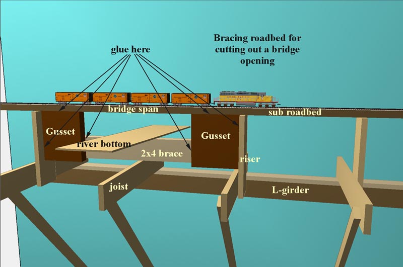
I've had good luck constructing a "U" shaped brace that I install
under the roadbed extending it to the nearest risers. The longer
the span, the more robust the construction of this brace needs
to be.
Refer to the diagram for an idea of how I build this brace.
It is very important that the gusset pieces fit tightly between
the roadbed and the risers. Two layers of 3/4" plywood laminated
together makes a decent gusset. The brace between the gussets
may be a 2x4 (as shown) or I sometimes use more plywood. For
a long span I'll add ribs or other additional bracing.
It was suggested on the layout construction yahoo egroups
list by Earl Hackett Jr. that the joint between the sub-roadbed
and the gussets be filled with epoxy for an extra strong joint.
You simply can't have too much strength here.
Here are Earl's comments from his email to the LC-list egroup. They
are aimed at adding a bridge in a location where the roadbed and sub-roadbed
are not already installed.
Here's what I did, and it's held position on two large bridges for 8 years now.
When I decided on a location for a bridge, I laid a piece of 3/4"
plywood directly on the table girders. This was screwed and glued
down so it wasn't going anywhere. This plywood extended to the table
girder past each end of the bridge location. Using sort of an inverted
L girder, the risers were attached to this sheet of plywood. One riser was
placed right at each end of the future bridge, and another about 6" inland.
The two risers at each end were connected by a gusset so they were held in
position relative to each other. These two closely spaced risers would hold
the subroadbed in alignment I cut them just short of the height needed to
connect with the subroadbed. Subroadbed was laid in position and allowed to
seek it's own level over the bridge area. I drilled a couple of holes in the
subroadbed directly over each riser and injected thickened epoxy into the gap
between the top of the riser and the bottom of the subroadbed. I used a
syringe, but you could just spring the subroadbed up a bit, pack the epoxy
on top of the riser, and let it back down. The next day you're ready to
remove the subroadbed where the bridge will go and nothing's going anywhere.
You can drill and countersink for a screw to add additional strength to the
roadbed/riser connection after everything is set.
With the roadbed already in place, this wouldn't be hard to do. Remove the
present risers, put the plywood in place and add new risers as needed. From
that point on, proceed as above. Having the cork already in place shouldn't
be a problem if you spring the roadbed up a bit so you can pack the epoxy
underneath it.
Being a boatbuilder, I've learned to use epoxy for all sorts of problems like this.
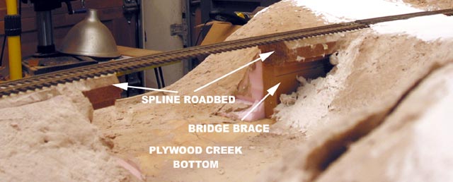
Bracing for the Jallen Causeway bridge.
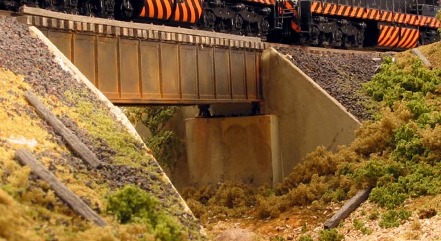
The finished bridge.